Inspect Elements Before Installation
Check each element for cracks, chips, or damage. Measure the resistance of each element with a multimeter. Elements in the same furnace zone should have resistance values within ±10% of each other for balanced heating.
Prepare the Furnace
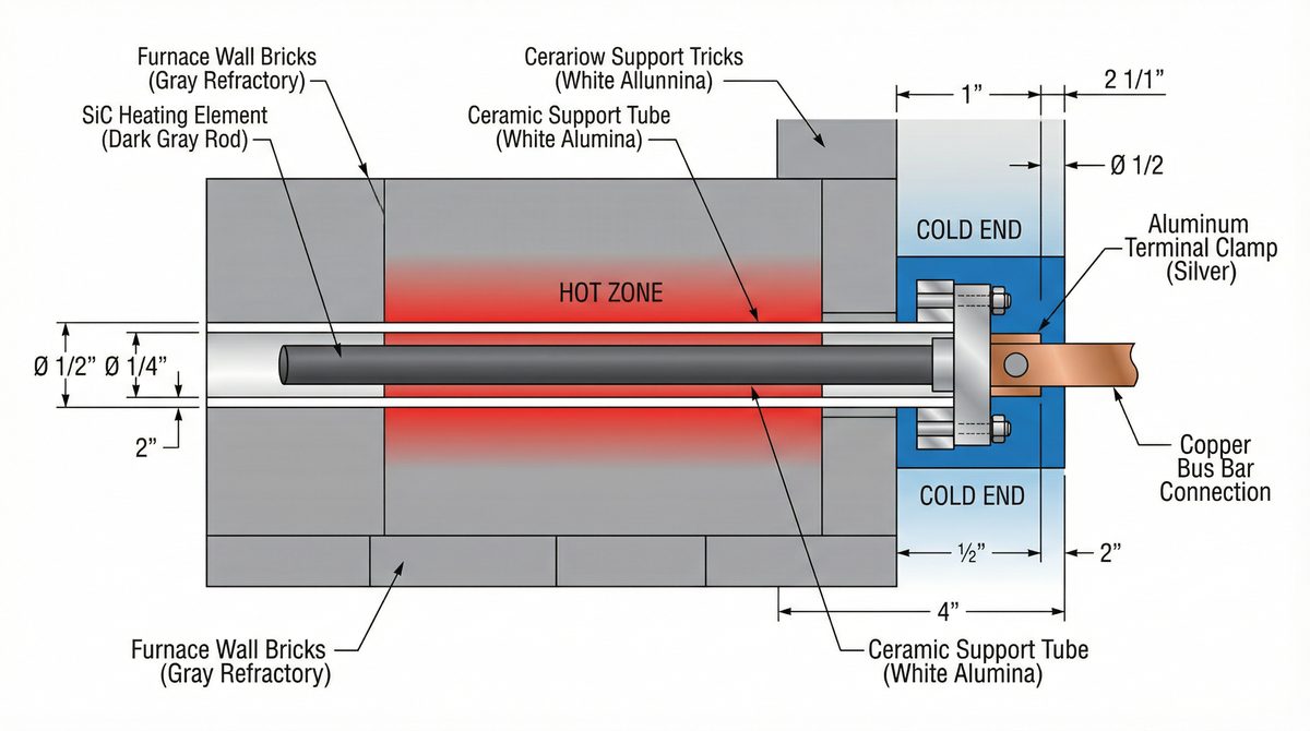
Ensure element holes in the furnace wall are clean and the correct diameter (element diameter + 2–3mm clearance). Install ceramic support tubes in the furnace wall to protect the cold ends and provide mechanical support.
Insert the Elements
Insert elements carefully through the support tubes. The hot zone must be fully inside the furnace chamber. The cold ends should extend at least 50mm beyond the furnace wall. Never force elements.
Connect the Terminals
Use aluminum clamps to connect the cold ends to the power supply cables. Ensure all connections are tight and secure. Connect elements in the correct configuration (series, parallel, or delta/star for 3-phase).
Initial Burn-In Procedure
New elements must be burned in gradually to oxidize the surface and stabilize resistance. Follow this schedule:
| Stage | Temperature | Duration | Purpose |
|---|---|---|---|
| Stage 1 | 200–400°C | 1 hour | Remove moisture |
| Stage 2 | 400–800°C | 2 hours | Initial oxidation |
| Stage 3 | 800–1200°C | 2 hours | Stabilize resistance |
| Stage 4 | Target temperature | 1 hour | Final conditioning |
Common Installation Issues
This is normal for new elements. After the burn-in procedure, resistance will stabilize. If resistance remains high, check that connections are tight and that the element surface is clean.
Check that all elements have similar resistance values. Elements with significantly different resistance will draw different power. Replace any elements that are outside the ±10% tolerance range.
SiC elements are brittle. Never apply bending stress or impact force. If an element breaks, contact Mr Pino for a replacement. Always handle elements with both hands and avoid dropping them.